Entropy Wave Generator for Combusto-Turbine interaction
Hot Streak Evolution in an Axial HP Turbine Stage
An experimental and computational study on hot streak evolution in a HPT has been recently launched at Politecnico di Milano. The results of the first experimental campaign on hot streak migration in the stator and in the rotor of an HPT model, for four different clocking positions between the hot streak and the stator blade, thus providing a unique dataset for flow analysis and computational model assessment.
Hot streaks were injected in different clocking positions with respect to the stator blade, and provide a total temperature perturbation representative of aero-engine conditions.
Several measurement techniques were applied to investigate the hot streak impact on the thermal and aerodynamic behavior of the stage.
It has been shown that, throughout the convection within the stator channel, the hot streak undergoes different migration and attenuation depending on the injection position. In particular, the clocking of the hot streak with the stator blade leading edge induces a dramatic deformation of the hot streak, which takes the shape of the blade wake. The temperature attenuation across the stator is severe for all the cases, and the maximum temperature ratio drops down from 1.2 to 1.05. With the exception of the injection on the suction side, a portion of the hot streak is entrained in the cross-flow induced by the stator pressure field on the shroud. A negligible increase in the stator total pressure loss is found due to the hot streak transport and evolution.
When the stator blade thermal stress is of concern, the hot streak injection on the leading edge is the worst possible operating condition, as can be argued by the temperature field downstream of the stator and as already pointed out by other authors . The Mid-Pitch case seems to guarantee the lowest interaction with the blade and the highest temperature diffusion all over the channel. On the contrary, downstream of the rotor the highest diffusion is found for the PS injection, with potentially positive implications on the following stage.
The expected over-speed induced by the hot streak due to its higher enthalpy content at the stator exit is very limited, although expected also by theoretical analysis, and has a minor impact on the rotor incidence angle. Conversely, an interesting effect is found on the vorticity field, which shows additional contributions at the top and bottom of the hot streak (except in the case of
leading edge injection). Such additional vorticity cores also alter the rotor secondary flows as found at the rotor outlet. The temperature disturbance at the rotor outlet is further attenuated, consistently, with a significant spreading of the incoming rotor disturbances. These results are in line with the enhanced
migration that the hot streak experiences in the rotating channel, and triggers the interest for further experimental and computational studies specifically oriented to the unsteady hot streak migration in the rotor. Due to the hardware limitations, hampering the flow field analysis over a 1/11 periodicity, no information can be drawn on the stage performance; such limits can be overcome by applying a computational fluid dynamic model.
Design of a combustor simulator combining swirl and entropy wave generation
Modern aero-engines combustion chambers burn a lean and premixed mixture generating a turbulent flame which involves large heat-release fluctuations, thus producing unsteady temperature phenomena commonly referred to as Entropy Waves (EW). Furthermore, to enhance the fuel air mixing, combustion air is swirled leading to vorticity disturbances. These instabilities represent one of the biggest challenges to face in gas turbine design. In this paper, the design and testing of a novel Entropy Wave Generator (EWG) equipped with a Swirler Generator (SG) is described. The novel EWG will be used in future works on the High Speed Test Rig at Politecnico di Milano to study the combustor-turbine interaction.
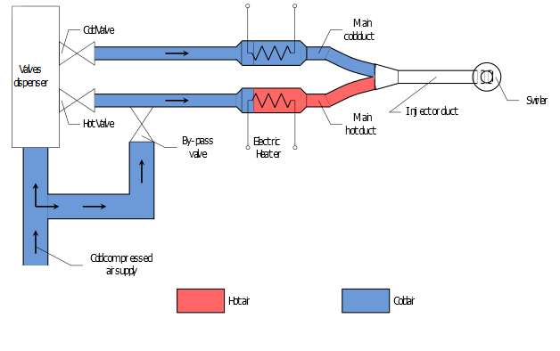
A set of automotive fuel injectors for methane fueled engines feeds alternatively two different ducts with electrical heaters installed: one branch has the electrical heater switched on (and for this referred to as “hot duct”) and the other has the heater switched off (“cold duct”). This geometry ensures the same pressure losses in the two branches. A by-pass valve is placed on the hot duct so that, when opened, the device works as a hot-streak generator bypassing the valves dispenser. The two ducts are coupled in the injector head which injects the alternated hot-cold air in turbine streamwise direction. In order to simulate the real aero-engine turbine inlet flow, at the injector outlet a Swirl Generator is placed.
The interaction between combustor and turbine became an important object of study and research since flow non-uniformities strongly affect the machine performance. The lightweight design management adopted by aero-engine manufactures, that reduce components spacing, aggravates this problem primarily in the first high pressure turbine stage. Considerable research efforts have been made for the characterization of the combustor incoming flow and its impact across the stage. Temperature non-uniformity consists of local steady and unsteady hot spots identified in literature as hot streak (HS) and entropy wave (EW), respectively. Passage and migration of these spots modify the flow quantities expected in the traditional
design phase altering the aero-thermal performance of the stage. The local high temperatures, that could damage blades, worsen the cooling system effectiveness and reduce the inlet achievable mean temperature directly impacting on the efficiency.
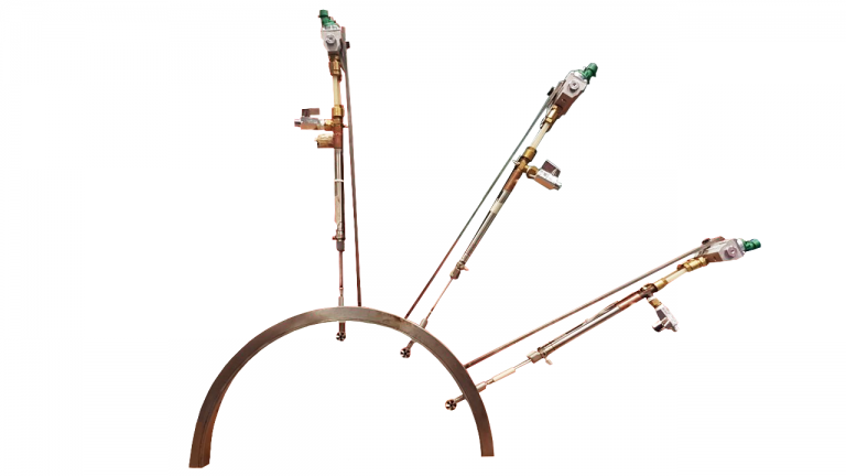
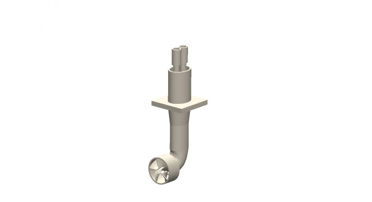
The swirler generator adopted is a bladed one. It contours the outside of the injector body so that the turbine main stream and part of the injected EW are put into rotation while only the central part of the pulsating flow is released. However, at a certain distance from the exit section, the core jet is forced into a swirling motion due to a momentum exchange with the surrounding flow, coming from the blades. The injector-swirl generator system is made of a chromium-cobalt alloy and the SG has five cantilever blades with an inlet angle of 20° and an outlet one of 40°. The number of blades is the one minimising losses in the swirler and it is based on the Ainley-Mathieson correlation.
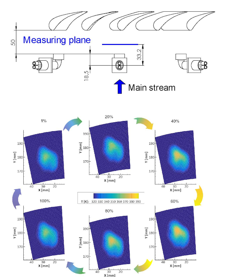
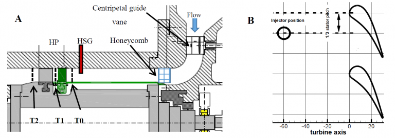
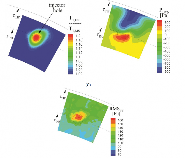
The EWG is placed upstream the turbine test rig to simulate the combustor unsteadiness that approaches the aero-engine turbine first stage. The investigation of these effects on the turbine aerodynamic will be object of future works. On the contrary, the main features of the unsteadiness produced by the novel designed EWG are described in this section. Figure 16 shows the measuring plane location with respect to the injector axis, the injector outlet section and the stator leading edge.
There are spots for 11 injectors on the turbine test rig making possible to have one injector each two stator blades (i.e. stator blades are 22). To carry out the aerodynamic and thermal assessment of the EWG only three injectors are mounted for a sake of simplicity. Measurements are done on the central of the three injectors, thus guarantying the periodicity.
Figure shows the peak-to-valley variation of the temperature profile in a valve period. It refers to a condition of 110 Hz, that is a period of around 9 ms. In the data reduction the period is divided into 100 frames; figure 17 shows frames at 1%, 20%, 40%, 60%, 80% and 100% of the period.
The novel EWG is the only documented in literature able to produce engine-representative entropy wave (or hot-streak) disturbances combined with swirl motion. The main advantage of the designed EWG is its versatility: it can be mounted on a test rig requiring only few modifications. To gain this versatility, the injector has a stem that produces a wake and makes slightly not symmetric the flow pattern produced. However, as shown in the wind tunnel experimental campaigns, the injector wake is fully recovered at a position representative of the stator inlet section. Furthermore, this device is able to produce an entropy wave, that is a temperature fluctuation perturbation, or a hot-streak, that is also swirled. In literature few devices able to combine hot-streak and swirled motion are documented, instead none combines entropy wave and swirl, notwithstanding that both features are unavoidable if combustor-turbine interaction is under study
Selected references
-
Notaristefano A.,Gaetani P., Design and commissioning of a Combustor Simulator featuring Swirl and Entropy Wave Generator, Int. J. Turbomach. Propuls. Power 2020
-
Persico, G; Gaetani, P; Spinelli, A. Assessment of synthetic entropy waves for indirect combustion noise experiments in gas turbines. Exp Therm Fluid Sci 2017, 88, 376-388
-
Gaetani, P; Persico, G; Spinelli, A. Coupled effect of expansion ratio and blade loading on the aerodynamics of a high-pressure gas turbine. Appl. Sci 2017, 7, 259
-
Persico, G; Gaetani, P; Paradiso, B. Estimation of turbulence by single-sensor pressure probes. XIX Biannual Symposium on Measuring Techniques in Turbomachinery 2008