Steady Measurements
Steady state calibration of 5-hole, 3-hole, cylindrical and total pressure probes
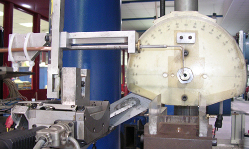
The facility allows the directional calibration of aerodynamic probes under different flow regimes in terms of Mach and Reynolds numbers.
Different rectangular semi confined nozzles (50 x 60 mm) for subsonic or supersonic probe calibration (up to Mach number 2.5) are available. The rectangular semi-confined nozzle section has been designed to properly simulate geometrical constrains of wind tunnels for turbomachinery applications.
A circular nozzle of 50 mm diameter can be used in order to simulate different Reynolds number independently from Mach number. The Reynolds number variation is obtained pressurizing the calibration section by means of downstream chocked conditions. The maximum total pressure on the calibration section is 20 bar.
On board instrumentation provides the reference flow characteristic in terms of static and total pressure and temperature. The probe can be rotate on pitch (± 25 deg) and yaw angles (360 deg) by means of stepping motors. The angle positioning accuracy is within 0.05 degree for both yaw and pitch rotations. The calibration procedure is fully computer controlled.
All types of 2D and 3D directional aerodynamic probes con be in principle calibrated. Typical calibration are multi-hole directional pressure probes, rotating directional pressure probes and hot wires.
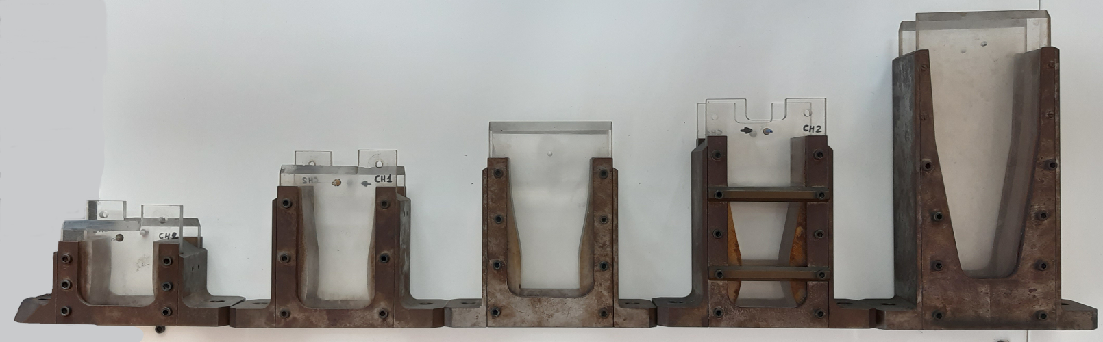
Several measurement techniques are available at the LFM for aerodynamic experimental researches. All probes can be assembled on high accuracy computer controlled 2D and 3D linear traversing and rotating system (from millimetres up to 4 m). Probes can be applied either in the LFM or in external facilities, depending on the rig constrains and operating conditions.
Besides conventional total and static pressure measurements as well as the temperature one, the following techniques are available:
-
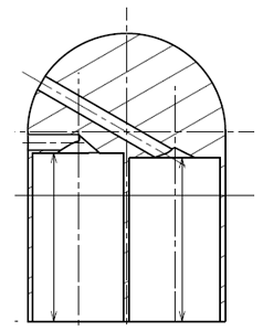
Directional miniaturized multihole pressure probes for steady 2D and 3D flow field application calibrated up to a Mach number of 2.5 and in a wide angular range (typically +/-24 deg. for the yaw and pitch angle).
-
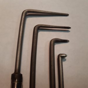
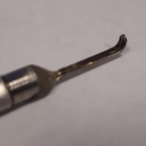
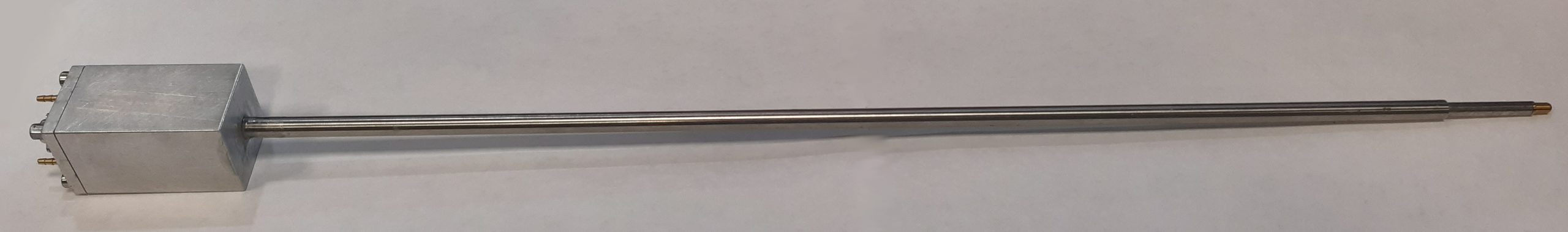
Directional miniaturized fast response pressure probes (FRAPP) for unsteady 2D and 3D flow field application up to 100 kHz; 2D probes can be applied up to sonic conditions and at a temperature up to 273°C.
-
Hot wire probes and anemometer for steady and unsteady measurement up to Mach=0.4 and 40 kHz
Fast Response Pressure Probe
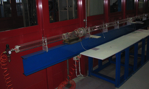
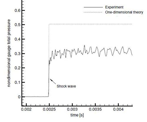
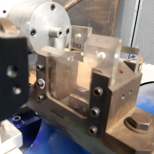
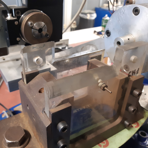
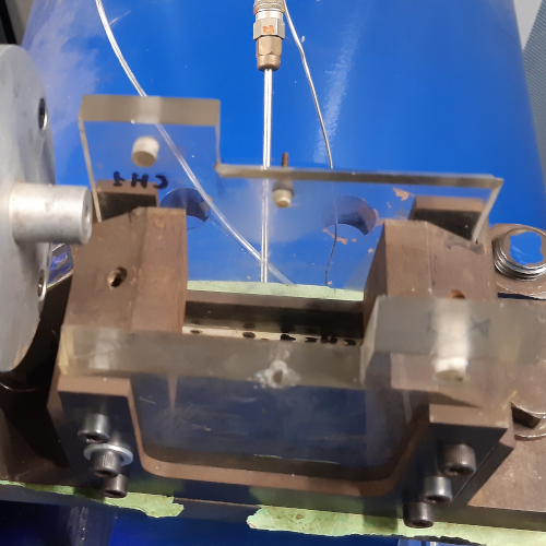
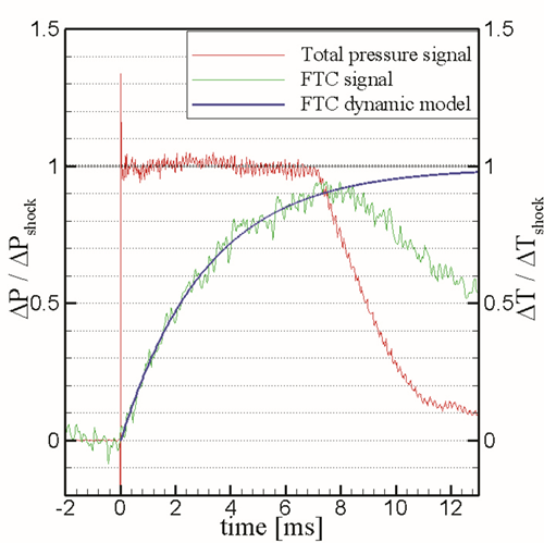
To dynamically calibrate pressure probes a shock tube was build in 2002 at LFM. The shock tube is built from a plexiglass tube with an internal diameter D of 80 mm and a thickness of 5 mm, to allow for continuous optical access along the whole pipe length (figure 1). The tube is divided into two sections by the diaphragm: the closed 1500 mm long high-pressure section and the open-end low-pressure section, whose length is 5000 mm. The low-pressure section of the shock tube is open to the ambient pressure; in the high-pressure part of the tube an overpressure typically of about 1 bar is maintained since the shock tube has been designed to produce a weak shock wave to be used in the dynamic calibration of fast-response pressure probes suitable for turbomachinery applications. To this purpose, the shock tube length has been chosen to allow for a relatively long time span (about 11 ms at 2750 mm from the diaphragm, where typically probes are inserted) of constant flow between the passage of the shock wave and the arrival of the rarefaction fan reflected from the tube closed end. The tube diameter has been chosen to minimize the blockage due to the insertion of one or two pressure probes, to simplify the diaphragm manufacturing and to reduce viscous effects related to the formation of the boundary layer behind the shock wave.
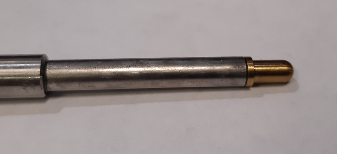
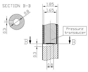
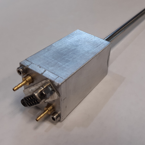
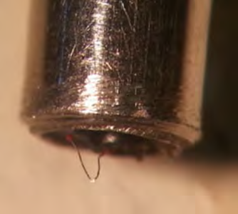
Reference pressure signals are measured by means of a miniaturized total pressure probe. The instrument consists of a piezoresistive pressure transducer (Kulite, model XCQ- 062, full scale = 1.72 bar (25 psi)) encapsulated in a stainless steel tube to enhance probe stiffness: the external diameter of the final probe head is 1.8 mm. The membrane of the transducer is flush mounted and it is protected by means of an RTV coating. According to the manufacturer’s data, the membrane resonance frequency without RTV coating is 350 kHz, while that measured with the coating has a value of 175 kHz.
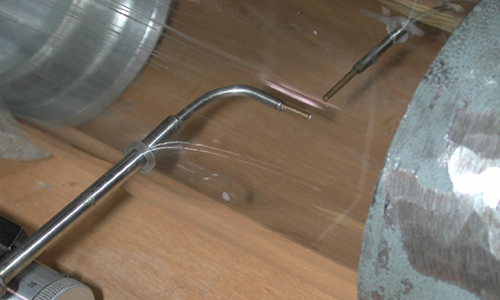
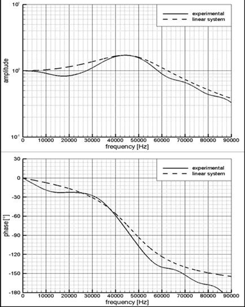
In low pressure applications plastic diaphragms are used; they automatically break under a given pressure difference have been employed to avoid the use of an ad hoc breaking system. The diaphragm bursting process has been studied by means of a high-speed camera (up to 50000 frames per second, namely, 20 µs time resolution): the total opening time is about 400 µs. An axisymmetric petalling starting from the centre of the diaphragm was observed (70–75% of the internal tube diameter) and the final opened section is almost circular. The pressure step differs from the 1D theoretical one and it is characterized by pressure oscillations superimposed on the pressure plateau: thanks to an in-house developed data reduction procedure, the transfer function both in terms of amplitude and phase, results extremely neat.
Given its features, the shock tube has been also used for testing line-cavity system facing pressure transducer located inside turbine blades.
Fast Response Micro Thermocouple
- Platinum / platinum rhodium:
- Wire diameter : 25μm;
- Frequency response up to 200 Hz, Mach < 0.6;
Dimension and material as trade-off between robustness and promptness