Two Buildings - Over 2000 sq m of surface available
Research on Fluid machines Aerodynamics and compressible fluid dynamics for renewable energy
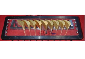
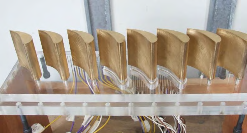
Test facility consists of a transonic and supersonic blow down wind tunnel for linear cascades. The test section, 400 mm wide in tangential direction, allows to install linear cascades with a relatively large number of blades, providing a high quality of flow periodicity. Cascades characterized by 50 mm or 80 mm height can be tested. The facility is supplied by means of an air storage of 6000 kg at 200 bar, allowing long testing time also in supersonic conditions. Maximum available flow rate is 7 kg/s. A secondary flow rate supply system is provided in order to perform aerodynamic measurements on film cooled blades.
The wind tunnel is equipped with a fully automated and computer controlled data acquisition and 3D traversing system, both upstream and downstream the cascade. Up to 100 pressure signals can be acquired during tests in order to define static pressure distribution on blade and endwall surfaces.
Typical measurement are performed with pneumatic directional probes (5 hole probes) and hot wires. Optical measurement are allowed by the installation of glass window in the test section: LDV and Schlieren can be easily performed. In particular, Schlieren technique is applied run-time when performing supersonic tests in order to check flow periodicity and shock patterns.
Low speed closed loop test rig for turbine axial stages
Large scale - High accuracy - Easy and Economical
Test facility consists of a subsonic-transonic closed loop wind tunnel for turbine stages. The flow rate is provided by a variable rotational speed centrifugal blower equipped with IGV, allowing a maximum capacity of 15 m3/s. The test section can house up to two full turbine stages with a maximum blade height of 200 mm and a maximum tip radius of 890 mm. The turbine is bracken by a two stage axial compressor equipped with IGV and variables stator vanes in order to increase the operational range. Compressor and turbine are installed on different shafts, connected through a high accuracy torque-meter. The maximum rotational speed is 5000 rpm; the fine setting of the rotational speed is guaranteed by an electrical brake (maximum 80 kW) operating on the compressor shaft. The extra compression ratio provided by the axial compressor allows a maximum expansion ratio of 2.1 on the turbine section.
The wind tunnel is equipped with fully automated and computer controlled data acquisition and 3D traversing system for detailed flow field measurements. A glass window allows the application of optical measurement techniques.
The facility has been mainly designed for detailed steady and unsteady aerodynamic measurements, but overall performance evaluation can be easily performed.
- Turbine Stage
- Torque Sensor
- Axial Compressor: 2 stages + IGV and VGVs
- DC Motor: 80 kW, 3000 rpm
- Centrifugal Blower: 500 kW, 20m3/s, βfan=1.2, variable speed;
- Venturi Nozzle
- Heat Exchanger
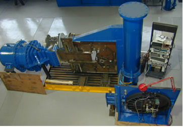
High Speed Closed Loop Test Rig For Axial And Radial Stages

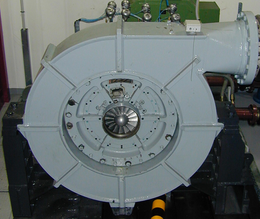
For the aim of research programs on axial turbines and centrifugal compressors a closed loop test rig for axial and centrifugal turbomachines has been launched in 2001 at LFM.
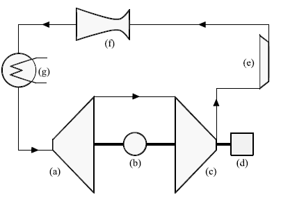
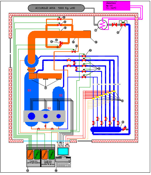
With reference to figure, the test rig is equipped with a section for centrifugal turbomachines (ref. 1 and figure 4) followed by a cooling section (ref. 3, 4), a Venturi nozzle for the flow rate measurement (ref. 5) and a filtering section (ref. 10); the pressurized flow rate can be exhausted either in the by pass line or in the axial section (ref.2). Flow rate regulation can be performed by two throttling valve sections (ref. 9, 10). The test rig can be operated under closed conditions or forcing the outlet or the inlet of the axial section to the atmospheric pressure; as an alternative the compressor can be connected to other LFM facilities through connection 6 and 7.
The maximum power available at the centrifugal section is 800 kW while 400 kW are available at the axial one; the maximum rotational speed is 20000 Rpm for both the sections. The two reversible DC engines allow a continuous rotational speed regulation and the electrical power generated at the turbine brake is reversed to the centrifugal section engine, leading to significant savings in electrical running costs.
Maximum centrifugal impeller diameter is 560 mm; maximum outer/internal diameters of the axial turbomachine are 400/280 mm.
The test rig is instrumented in order to allow the over-all performance evaluation of both installed turbomachines. Both sections are equipped with traversing systems for the measurement of the flow field inside and downstream of the turbomachines; optical accesses for LDV measurements are also provided.
At the present time, the centrifugal section is equipped with a centrifugal compressor characterized by a nominal compression ratio of 2.6 at 5 kg/s (inlet at atmospheric condition) at a rotational speed of 18000 rpm.
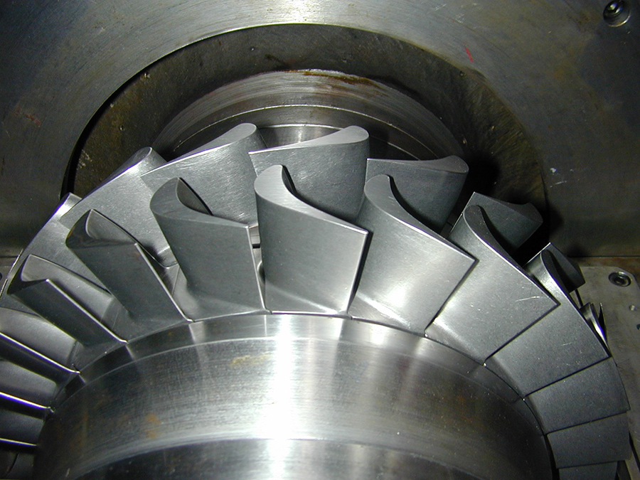
The axial section is equipped with an axial turbine (figure 3) representative of a modern HP stage characterized by a leaned stator and a bowed rotor rotating at 12000 Rpm; the casing diameter is 400mm and the blade height is 50 mm.
Safety Valves Test rig
In accordance with ISO-4126: safety devices for the protection against excessive pressure
Presso il Laboratorio di Fluidodinamica delle Macchine è operativo da oltre 20 anni un Impianto di prova specificatamente dedicato alla verifica delle caratteristiche funzionali e delle capacità di efflusso di valvole di sicurezza operanti in aria e in acqua. Le prove sono normalmente svolte per attività di R&D o per la valutazione delle caratteristiche necessarie alla certificazione di prodotto.
L'impianto prove in aria opera secondo il Sistema di Qualità Politecnico. Le attività sperimentali su valvole di sicurezza in aria, eseguite in accordo a norme tecniche (ISO 4126-1) o procedure interne, sono state verificate con esito positivo per conformità alla UNI EN ISO 9001-2000 e in base alle linee guide desunte dalla norma ISO 17025, fin dal 1999.
Il laboratorio è attrezzato in modo da poter eseguire prove in presenza di contropressione imposta o generata.
Le variabile fisiche generalmente rilevate durante le prove sono :
-
-
- pressione di sfioro
- pressione di richiusura
- contropressione
- portata reale/coefficiente di efflusso ( anche in presenza di contropressione imposta o generata)
- alzata otturatore.
-
The hydraulic test rig for pumps and turbines allows a maximum pressure of 10 bar and a maximum flow rate of 100 l/s. The test rig can be operated both in closed and open configuration. In closed configuration the plant pressure can be set in a dedicated piezometric tank by a pressurized air supply system or by a vacuum pump. The flow rate can be supplied by two pumps operating in parallel or in series mode; in order to precisely and independently control flow rate from total head, one pump is driven by a variable rotational speed DC motor.